- About
- Solutions
- Governance
- Investors
- Sustainability
- Sustainability
- Newsroom
- Jobs
The optical inspection of kilns, furnaces, and metallurgical vessels to estimate the residual refractory lifetime before local repairs or a complete relining is common practice in high-temperature industries. Most customers rely on nondigital refractory evaluation, for example physical measurements performed by personnel, with the drawback of long waiting times during cool down until the kiln can finally be entered safely. To minimise these downtimes by using digital optical inspections that enable data driven decisions, RHI Magnesita applied 3D laser scanning in cold conditions as a first step in optimising refractory lining assessment at the copper producer Kovohuty a.s. (Slovakia). Measurements were performed inside two different furnaces after a complete relining or during a typical inspection stop, to create an accurate reference for later comparisons. Another approach was additionally applied using 3D computer aided design (CAD) models, created out of a combination of 3D scanning and technical lining drawings. The results revealed the applicability of 3D laser scanning even for furnaces with complex shapes and structures, showing the potential of this technology combined with CAD based references, also in hot lining conditions.
RHI Magnesita regularly employs 3D laser scanning technology using terrestrial scanners to perform wear analytics of multiple vessel types in the steelmaking industry [1,2]. Scanning different lining conditions is typically performed in the cold lining state by on-site personnel within a few minutes, followed by automated analytics on a web-based cloud platform. Alternatively, mobile service technicians from RHI Magnesita, responsible for a group of customers, are specially trained to accompany refractory trials in any vessel using this mobile equipment. The data processing and visualisation are then carried out offline, followed by the delivery of a final 3D report. As a next step, this article provides further insights into the implementation of the same technology—on the one hand, under hot conditions in nonferrous furnaces, and on the other hand, as a potential approach to eliminate the need for scanning every vessel condition prior to the report generation.
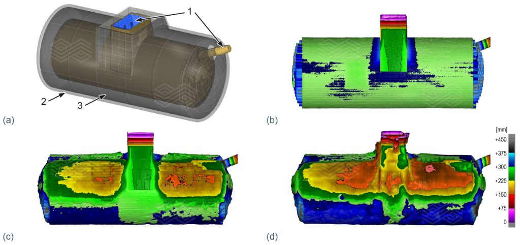
During a standard measurement procedure, the terrestrial laser is positioned scan-by scan around the vessel or inside the furnace or kiln, capturing both the refractory surface as well as some fixed steel structures positioned near the refractory lining. These structures are mandatory and provide essential reference points that ensure precise alignment of a newly created point cloud with previous scans of the same vessel or kiln. This solution is currently applied to electric arc furnaces (EAFs), ladles, RH degasser lower vessels, and blast furnace runners, using a web-based visualisation tool, as shown in Figure 1.
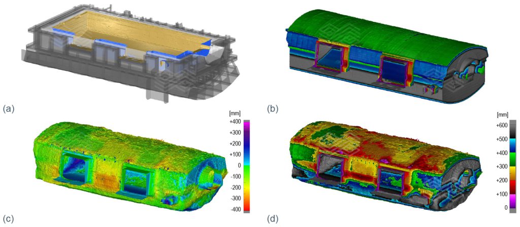
Parallel to this solution for the iron and steel industry, a similar approach has also been implemented for rotary kilns in the cement industry [3,4]. RHI Magnesita offers these kiln inspections and can identify areas and sections requiring repair within just a few hours. The results, including a report and point cloud evaluations are also available online via the web-based cloud platform, as illustrated in Figure 2. This service is accessible through the RHI Magnesita Customer Portal [5].
Unlike the scanning and evaluation of vessels with similar geometries, which enables a standardised and online process as described above, the application to sporadically scanned vessels and/or furnaces with complex dimensions requires an offline approach with manual evaluation methods. Furthermore, a major limitation of irregular scans is the frequent lack of reference data, such as scans of a complete relining, repair, safety lining, or the steel shell. Since these vessels are in operation for years, waiting for an available timeslot to generate these reference scans would significantly delay the creation of final reports and useable insights. To mitigate this issue, RHI Magnesita now uses computer-aided design (CAD) based references to accelerate this process. The advantages and limitations of this approach will be discussed in the following sections, comparing theoretical data from technical drawings with actual scan results as well as combining the two.
Kovohuty a.s., located in Krompachy (Slovakia), produces copper anodes via a pyrometallurgical process, using a shaft furnace, converter, anode furnace, and a separate holding furnace [6]. To evaluate the benefits of 3D scanning and CAD based models, the technologies were applied on the anode furnace as well as the holding furnace under various lining conditions—before, after, and during operation—covering both cold and hot furnace states.
Generating a 3D CAD image of a refractory lining or steel shell typically involves combining RHI Magnesita’s technical lining drawings with information from the 3D scans of the outer furnace and surrounding infrastructure, acquired during the refractory lining scanning process. This combination ensures a high level of accuracy and enables identification of potential improvements in both mechanical (shell) and refractory design. Furthermore, this approach of creating theoretical references eliminates the need to scan safety linings, which is sometimes not possible due to installation of the wear and permanent lining at the same time.
Figure 3 shows various stages during a holding furnace lining inspection. In Figure 3a the measured wear lining (1), the redrawn steel shell of the kiln (2), and the redrawn safety lining (3) are shown. In particular, the measured wear lining (1) and the redrawn safety lining (3) serve as references to calculate the wear after a campaign and determine the residual brick length (RBL). The segmented colour code depicts the initial RBL after relining (Figure 3b) and makes the identification of high-wear areas over time (Figures 3c and 3d) easy for the operator.

Figure 3. Various stages during a holding furnace lining inspection: (a) measured lining scan (1), CAD model (grey) of the steel shell (2), and redrawn safety lining (3), (b) RBL values after relining generated from the steel shell CAD model and measured lining scan, (c) RBL values after campaign 1, and (d) RBL values after campaign 2.
As with the holding furnace at Kovohuty a.s., 3D scans of the anode furnace were performed under various conditions by both RHI Magnesita and customer personnel. To complete the reference model, Kovohuty a.s. also provided steel structure scans from a third party, enabling the creation of a CAD model through the combination of scan data and technical drawings.
The images in Figure 4 are similar to those presented in Figure 3, but highlight the applicability of this CAD approach to even larger kilns. Another detail worth mentioning is the importance of selecting the correct colour coding for presenting the results to the operators. The standardised one-code version of Figure 4c was considered to lack a certain level of detail for identifying critical areas requiring repair actions. However, the subsequently developed segmented colour edition (Figure 4d) supports decision-making more effectively and is now the default in RHI Magnesita 3D reports.

Figure 4. Various stages during an anode furnace lining inspection: (a) steel shell structure (grey) with redrawn permanent lining (white), and measured unused wear lining (gold), (b) RBL after relining, (c) RBL after operation with typical colour code, and (d) RHI Magnesita’s colour code applied to (c).
Hot scanning a complete lining on a regular basis is challenging—not only technologically and from a health and safety perspective, but also financially. In the steel industry, standard measurement procedures often require placing the laser inside the vessel to obtain a full 360° scan of the lining condition. To avoid high investment costs and provide a more flexible solution, RHI Magnesita now applies the same scanning technology used for cold conditions to perform hot scans. This streamlined approach focuses on capturing the critical areas of the kiln necessary to safely continue production.
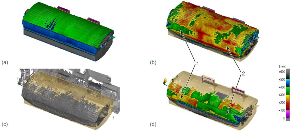
To ensure the safety of both operators and equipment, the measurements are performed at an adequate distance in the immediate vicinity of the hot furnace. As a result, the inspection area is restricted to the field of view available through the furnace’s charging doors. Figure 5 illustrates the results from this approach, with Figure 5a showing the RBL on the back region of the furnace before operation. The RBL of the kiln roof and back before a local repair is depicted in Figure 5b, while the hot measurement, performed approximately 6 months later, is shown in Figure 5c. The grey-coloured area depicts the inspection area accessible during the hot measurements, compared to the gold-coloured unused lining, captured under cold conditions with the scanner inside the furnace.

Figure 5. Various stages during an anode furnace lining inspection: (a) RBL of the unused wear lining, (b) RBL before repair (cold condition scanning), (c) measured area after repair indicating the inspection area accessible (grey) during the hot measurements compared to that captured under cold conditions (gold) with the scanner in the furnace, and (d) RBL after repair, measured in hot condition.
By combining the hot scan data with the CAD model and the unused lining reference, the resulting RBL values shown in Figure 5d were generated. The right half of the back region (2) of the furnace was repaired and now exhibits a uniform RBL (green) in this area. Similar actions were performed in certain roof sections, where previously worn areas (yellow/red) were relined (green). In contrast, the left half (1) of the back region was not repaired and shows a noticeably reduced RBL, compared to the same area in Figure 5b.
RHI Magnesita’s digital, time-efficient, and cost-competitive approach to evaluate refractory wear is established technology that can enhance productivity across various industries, such as iron and steelmaking as well as the cement sector [1–4,7]. However, due to the complex geometries of certain vessels—such as copper furnaces—automated reporting of lining wear is often not feasible. By combining manual evaluations with advanced measurement and analysis methods, including CAD models derived from technical drawings and scanned surfaces, highly accurate results can still be achieved. This approach eliminates common limitations like missing reference scans and significantly accelerates result generation and decision-making. Additionally, hot scanning allows condition assessment without stopping the kiln operation, saving time and production stops for cool downs, thus increasing the overall productivity. As demonstrated in the two use cases at Kovohuty a.s., RHI Magnesita is combining reality capture and CAD technologies to optimise refractory performance systematically and accelerate the process to a completely new service level.
[1] Santos, J.P., Macedo, J., Avila, H., Lima, G., Arruda, E. and Lazaroni, A. Innovative Refractory Wear Measurement Method for Steel Ladles Using 3D Laser Scanning. Bulletin. 2023, 57–60.
[2] Arth, G., Merta, L., Hechu, K., Luchini, B., Beukema, F. and Wortel, E. Deformation and Wear Analytics in Reheating Furnaces Using 3D Laser Measurement Technology. Bulletin. 2024, 82–86.
[3] RHI Magnesita. RHI Magnesita and Cement Industry. Expanding Horizons with Sustainable Solutions and Reliable Refractories in India, West Asia and Africa. Cement and Building Materials Review. 2024, 97, 38–41. Presented at the 27th Arab International Cement and Building Materials Conference and Exhibition (AICCE27), Tunis, Tunisia, November 26–28, 2024. http://aucbm.net/uploaded%20Files/Magazine/Magazine_97_TwoParts.pdf
[4] https://www.youtube.com/watch?v=8foQjHhAjy4
[5] https://customerportal.rhimagnesita.com/home
[6] https://www.kovohuty.sk/home.html
[7] Ribeiro, A., Nogueira, A., Schütz, J., Menezes, E., Araújo, R.D. and Domiciano, V. Advanced Technology Package for Blast Furnace Runners Focusing on Operational Safety, Availability, and Refractory Performance. Bulletin. 2021, 84–89.