- About
- Solutions
- Governance
- Investors
- Sustainability
- Sustainability
- Newsroom
- Jobs
Off-centre and angled pouring of molten steel into the tundish by a misaligned ladle shroud can result in several problems caused by the asymmetric flow, such as short-circuiting flows, inhomogeneous temperature distribution, and a higher tendency of vortex formation with consequent slag entrainment. Although many different impact pot designs are available in the industry, to date none have effectively addressed the issue of asymmetric flows caused by off-centre pouring. This paper presents the development of a novel impact pot design that can perform well even under such adverse conditions, as shown by mathematical and physical modelling studies.
The tundish is an important vessel in the continuous casting process, connecting the incoming steel flow from the ladle to the moulds. In the past, the role of the tundish was limited to distributing molten steel to the moulds, enabling continuity of the casting process even between ladle changes. As the requirements for quality became more severe, flow optimisation in the tundish was afforded more consideration, as steelmakers worked to make this vessel a place of further molten steel refining. The impact pot has several important functions in a continuous casting tundish, including:
The effectiveness of a given impact pot in complying with these requirements depends largely on its geometric features. Figure 1 shows the effect of the impact pot inner geometry on the internal flow pattern of the steel. The internal features of the impact pot design influence the flow velocities, dissipating the kinetic energy of the entry jet [1].
The effects of different flow control devices have been thoroughly studied by many researchers [1–5]. What all these studies have in common is they show that the influence of the impact pot design on the tundish flow pattern is very significant. Various techniques, such as physical modelling and numerical simulation, have been adopted to assess the effectiveness of alternative impact pot geometries in improving the tundish flow pattern.
One operating condition of concern is when the incoming jet from the ladle is not centred in the impact pot. Most impact pots are designed under the assumption of a perfectly centred jet, which is often not true in the real casting process. As a result, many impact pots underperform when subject to off-centre jet conditions, as the resulting tundish flow becomes asymmetric, presenting issues such as:
Although there is a high number of publications about new impact pot designs, none has yet effectively addressed the issue of asymmetric flows caused by off-centre pouring. This paper presents the development of a novel impact pot design that can perform well even under such adverse conditions, as shown by mathematical and physical modelling studies. The modelling methods will be further detailed in the next section.

Figure 1. Effect of the impact pot internal geometry on steel flow [1].
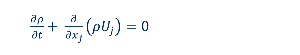
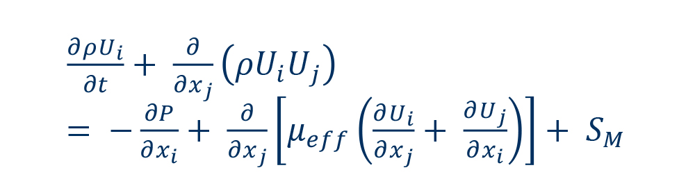
Computational fluid dynamics (CFD) modelling solves the Navier-Stokes equations for continuity and momentum (equations 1 and 2):
 |
(1) |
 |
(2) |
Where ρ is the fluid’s density, t is the time, xj is the coordinate in the j-direction, Uj is the velocity component in the j-direction, P is the pressure field, SM is the sum of the body forces, and μeff is the effective viscosity accounting for turbulence given by equation 3:
 |
(3) |
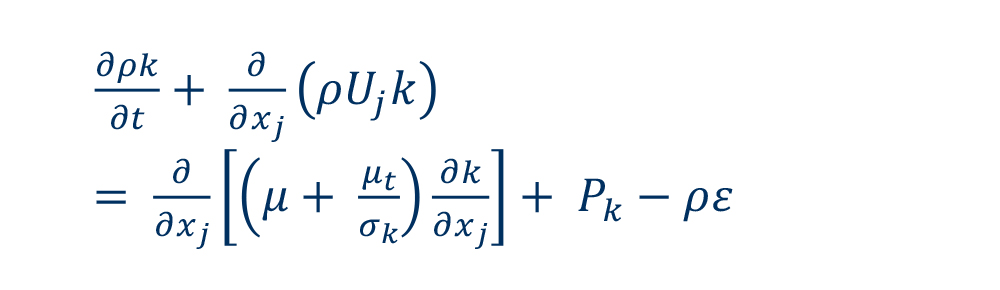
Where μ is the fluid’s molecular viscosity, Cμ is a constant, k is the turbulent kinetic energy, and ε is the dissipation rate of turbulence [1].
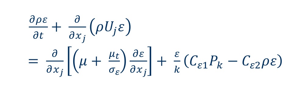
Equations 4 and 5 represent the transport equations for turbulent kinetic energy and dissipation rate of turbulence:
 |
(4) |
 |
(5) |
Once the flow field has been calculated, a residence time distribution (RTD) analysis is performed to characterise the flow according to the definitions of plug volume, dead volume, and mix volume [6]. To conduct the RTD study, a numerical simulation of tracer transport in the calculated flow field is performed. The transport equation for the tracer is given in equation 6:
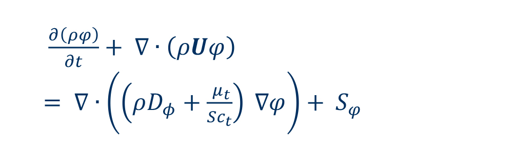 |
(6) |
Where φ is the tracer concentration, Sct is the turbulent Schmidt number, Sφ is a source term for the concentration, µt is the eddy viscosity, and Dφ is the kinematic diffusivity of the tracer [1].
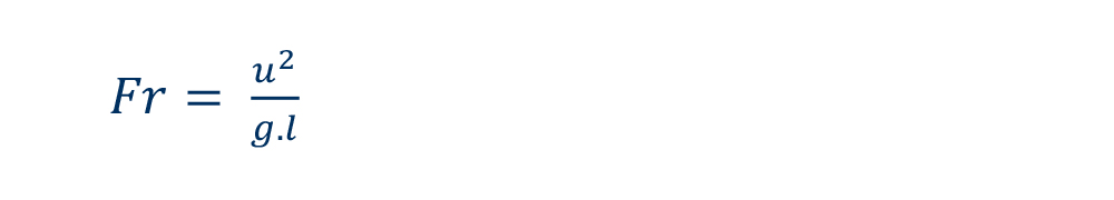
The practical experiments were carried out using a model representing a twin strand slab casting tundish without any additional flow modifiers except an impact pot. The water model was operated on a scale of 1:3, fulfilling Froude similarity. According to the literature [7], this approach is most likely to simulate flow phenomena of the corresponding full-scale system accurately. The Froude number, which is the ratio between inertial and gravitational forces, is defined by equation 7:
 |
(7) |
Where u is the flow velocity, g is the gravitational acceleration, and l is the characteristic length of the system [1]. Table I provides information on the operating conditions considered in the model and values of the real application.
To characterise the flow performance of the given tundish setup, the stimulus response technique, in which the concentration of an injected tracer fluid (e.g., dye) is recorded at the outlets, was applied. Analysis of the measured curve provides key information on the flow characteristics in the tundish such as the minimum residence time and other parameters. Besides the dye concentration measurements, a video was recorded synchronously to get an impression of the general flow characteristics [1].

Table I. Operating conditions in the water model and the real application.
The first step in the development of a solution to avoid asymmetric flows into the tundish was to understand in detail how the flow develops in the impact zone when an off-centre jet situation occurs. A two-strand slab tundish was chosen as a reference for this study. Figure 2 shows the tundish geometry and positioning of the off-centre jet in the impact pot.

Figure 2a. Schematic of the tundish setup.

Figure 2b. Off-centre jet position in the impact pot.
After the incoming jet enters the impact pot, it circulates inside the box and then flows upward towards the slag layer. This process dissipates some of the kinetic energy of the jet, reducing the average velocities of the flow downstream and is one of the reasons impact pots are widely used in the industry.
Figure 3 shows the velocity contours on the bottom surface of the impact pot and Figure 4 depicts the contours of the upward flow velocities as a cross section of the impact pot’s top surface, with both figures comparing centred (Figures 3a and 4a) and off-centre jet conditions (Figures 3b and 4b).

Figure 3a. Velocity contours on the bottom surface of the impact pot for centred jet conditions.

Figure 3b. Velocity contours on the bottom surface of the impact pot for off-centre jet conditions with the impingement point at the bottom left.

Figure 4a. Cross section of the upward flow distribution on the top surface of the impact pot for centred jet conditions.

Figure 4b. Cross section of the upward flow distribution on the top surface of the impact pot for off-centre jet conditions.
The results illustrate that for the centred jet case, the flow is distributed evenly across the cross section, which would result in a symmetric flow into the tundish, as the flow is distributed equally in all directions. However, for the
off-centre case, the upward flow is strongly concentrated on the opposite side of the incoming jet, as that is the path of least resistance. Such behaviour would very likely result in an asymmetric tundish flow, as there is a clear preferred flow direction. Figure 5 shows contours of the flow on the top surface of the molten steel bath, downstream of the contours shown in Figures 3 and 4, comparing the centred and off-centre conditions. An asymmetric tundish flow can be clearly observed for the off-centre case, in all directions (Figure 5b). Figure 6 shows dye dispersion pictures taken from the front of the tundish at the same flow time in the experiment (i.e., 10 seconds) for both configurations in the water modelling study. The asymmetry of the flow field in the off-centre jet configuration can also be clearly seen, with the incoming jet off-centre to the left side and the downstream flow asymmetric towards the strand on the right side.
If it occurs in a real caster, an asymmetric tundish flow is likely to cause several issues, including accelerated and uneven refractory wear in the region of the preferred flow path, temperature and steel chemical composition differences between strands, shorter residence times, nonmetallic inclusions flowing into the moulds, and a higher tendency of vortex formation due to the rotational flow. Such a scenario created the strong motivation to develop an alternative impact pot solution that would be able to handle off-centre jet conditions, which unfortunately are common in real casters.

Figure 5a. Contours of the flow on the top surface of the molten steel bath for centred jet conditions.

Figure 5b. Contours of the flow on the top surface of the molten steel bath for off-centre jet conditions.

Figure 6a. Snapshot of the dye dispersion in a water modelling experiment at t = 10 seconds for centred jet conditions.

Figure 6b. Snapshot of the dye dispersion in a water modelling experiment at t = 10 seconds for off-centre jet conditions.
An impact pot designed to work well even under off-centre jet conditions must, on a fundamental level, equalise the upward flow distribution at its top opening cross section. The upward flow out of the impact box is typically skewed towards the path of least resistance, which is the opposite side of the incoming jet. Only by having an even flow distribution out of the impact pot can a symmetric tundish flow be obtained.
An effective solution for off-centre jet conditions has been obtained with an impact pot design comprising a plurality of vertical barriers arranged below several horizontal barriers. The vertical barriers’ working principle consists of breaking the asymmetrical horizontal velocity components of the liquid metal flow and promoting ascending flow throughout the entire horizontal cross section of the impact pot. This effect minimises the concentrated upward flow at the opposite side of the entry jet. However, the vertical barriers alone are not enough to homogenise the flow since different vertical channels (between adjacent vertical barriers) can have different flow velocities. Therefore, to achieve proper flow homogenisation, horizontal barriers are positioned at some distance above the vertical channels. As a result, the liquid metal flowing upwardly through the vertical channels collides with horizontal barriers and homogenises the flow. Such homogenisation occurs due to the mixing generated as the flows from adjacent vertical channels are forced against each other. Another beneficial effect is dissipation of the flow’s kinetic energy caused by the longer path the fluid needs to take to go around the horizontal barriers after colliding with them. The combination of both vertical and horizontal barriers provides a homogeneous flow out of the impact pot and into the tundish, even under the unfavourable conditions of a misaligned ladle shroud.
This effect is shown in Figure 7, where the velocity contours on the bottom surface and at the top opening of the impact pot are displayed. The prior art design shows velocity vectors following the path alongside the impact pot walls, which causes most of the fluid to flow upward in a concentrated stream located at the opposite side of the box relative to the impingement point. The vertical barriers disrupt such motion, causing fractions of the flow to be entrapped in the vertical channels formed by adjacent vertical barriers. Such an effect, in combination with the flow kinetic energy dissipation caused by collision of the upward flow with the horizontal barriers located above the vertical channels, avoids the concentrated flow behaviour, as the fluid is forced upward along the entire perimeter of the impact box. Comparing the distribution of the upward flow along the top surface of the impact pot, the new development provides a significantly more even flow distribution, minimising concentrated flow spots and reducing dead zones. Consequently, asymmetry of the tundish flow is also significantly reduced, as it can be seen in Figure 8.

Figure 7a. Effect of vertical and horizontal barriers in disrupting the asymmetric flow caused by off-centre jet conditions. Velocity contours on the bottom surface of the impact pot for the prior art design.

Figure 7b. Effect of vertical and horizontal barriers in disrupting the asymmetric flow caused by off-centre jet conditions. Velocity contours on the bottom surface of the impact pot for the new development.

Figure 7c. Effect of vertical and horizontal barriers in disrupting the asymmetric flow caused by off-centre jet conditions. Cross section of the upward flow distribution on the top surface of the impact pot for the prior art design.

Figure 7d. Effect of vertical and horizontal barriers in disrupting the asymmetric flow caused by off-centre jet conditions. Cross section of the upward flow distribution on the top surface of the impact pot for the new development.

Figure 8a. Contours of the flow on the top surface of the molten steel bath for off-centre jet conditions for the design with exclusively horizontal barriers.

Figure 8b. Contours of the flow on the top surface of the molten steel bath for off-centre jet conditions for the new development.
Another comparison between the new development and designs with exclusively horizontal barriers or exclusively vertical barriers can be seen in Figure 9, where a lateral view is depicted, and the incoming jet impinges off-centre to the right. When there are only horizontal deflectors, the concentrated jet on the left side is clearly visible and an angled and strong upward flow from right to left occurs (Figure 9a). For the configuration with exclusively vertical barriers, even though it avoids the concentrated or angled upward jets, it shows the disadvantages of lacking mechanisms to dissipate kinetic energy, as this is typically achieved by collisions of the upward flow with horizontal barriers. Thus, stronger upward velocities are seen in this case (Figure 9b). The absence of horizontal barriers also makes it not possible to homogenise the flow between adjacent vertical channels, as achieved by the new development, which is a crucial aspect of avoiding asymmetric flows into the tundish.

Figure 9a. Lateral view of the tundish with an impact pot design comprising horizontal barriers. The incoming jet impinges off-centre to the right.

Figure 9b. Lateral view of the tundish with an impact pot design comprising vertical barriers. The incoming jet impinges off-centre to the right.

Figure 9c. Lateral view of the tundish with the new impact pot development. The incoming jet impinges off-centre to the right.
Figure 10 shows a comparison of the three different designs performed using water modelling experiments. The design with horizontal barriers (Figure 10a) displays a strong bias towards the right strand already at t = 10 seconds, whereas the design with exclusively vertical barriers has a bias towards the left strand at t = 20 seconds (Figure 10b). The best results in terms of mitigating asymmetric flow were obtained for the new development, with no bias towards any of the strands (Figure 10c).

Figure 10a. Dye dispersion snapshots of water modelling experiments with an impact pot design comprising horizontal barriers at t = 10 seconds and t = 20 seconds.

Figure 10b. Dye dispersion snapshots of water modelling experiments with an impact pot design comprising vertical barriers at t = 10 seconds and t = 20 seconds.

Figure 10c. Dye dispersion snapshots of water modelling experiments with the new impact pot design at t = 10 seconds and t = 20 seconds.
Figure 11 shows the RTD curves obtained for the three compared configurations. The designs with exclusively horizontal barriers or exclusively vertical barriers show visible differences between the curves for each of the strands, which is a quantification of asymmetry in the tundish flow. In contrast, the new development shows an almost perfect match between the curves for each strand, even though the incoming jet was asymmetric. These results confirm the effectiveness of this design as a solution for avoiding asymmetric flows into the tundish.

Figure 11a. RTD curves of an impact pot design with horizontal barriers.

Figure 11b. RTD curves of an impact pot design with vertical barriers.

Figure 11c. RTD curves of the new impact pot development.
Once the effectiveness of the solution developed for avoiding asymmetric flows into the tundish had been validated through water modelling experiments, the next step was to understand which design variables were most influential on the desired outcome. Such a study was performed through a design of experiments (DOE) in which each sample was the CFD result for a different design. About 250 different designs were simulated and the corresponding minimum residence times for each sample were plotted in a chart (Figure 12). For each strand, the minimum residence times were normalised according to the average minimum residence time obtained among all the samples. If the chart is divided in four quadrants, with the axes located at the normalised average value for all samples, the results shown in the top-right quadrant will be the samples with an above average minimum residence time for both strands. From a practical perspective, this is the most desirable outcome, as higher minimum residence times are associated with several benefits for the process and ideally should be obtained for both strands. Analysing the plot, it can be concluded that, from all the samples simulated, only a fraction of those are desirable designs. Therefore, by studying the design dimensions of the desirable designs compared to the full design range evaluated, some insights about the influence of each design parameter can be obtained.

Figure 12. Plot of the normalised minimum residence times obtained for each strand of each design.
For example, this method can be applied to evaluate the influence of the height of the vertical barrier, as shown in Figure 13. Even though an equal number of designs were simulated for each range of this design parameter, it was only above a certain threshold value that the designs were in the desirable quadrant. This means that not only the height of the vertical barrier is an important design parameter, but also that it should not be too low, otherwise its effect on the flow will not be noticed and the design will fail to work as it should. Such information is very relevant to design effective impact pots for several different steel plants that might each require a tailor-made solution. The same method can be applied to other design parameters of interest, such as protrusion length of the vertical and horizontal barriers, angles of the barriers, and distance between the barriers.
Figure 14 shows a representation of a specific design that performed very well in the simulations and experiments described in this paper, following the concept of the novel development. The next steps planned are to perform plant trials with this new development and measure the improvements obtained in the caster, particularly when
off-centre or angled jet conditions are present.

Figure 13a. Desirable range of the vertical barrier height. Number of simulated designs for each vertical barrier height range.

Figure 13b. Desirable range of the vertical barrier height. Number of good designs and vertical barrier height range.
.</p>")
Figure 13c. Desirable range of the vertical barrier height. Diagram indicating barrier height measurement (red arrow).

Figure 14. Novel impact pot design that performs even under off-centre jet conditions.
The combination of CFD simulations and appropriate DOE methods can provide a deep understanding of how to design an effective impact pot for any desired purpose. The premise of this paper was to develop a novel design to solve the issue of asymmetric flows caused by off-centre pouring into the tundish. The effectiveness of the new solution was confirmed by water modelling experiments, in which it was compared to prior art designs, in particular to designs following the concept of having exclusively horizontal barriers or exclusively vertical barriers. The results from dye dispersion experiments and RTD analysis demonstrated that the novel design was the only effective solution for avoiding asymmetric flows into the tundish, subject to an off-centre pouring condition. This innovative solution illustrates the potential of modelling and simulation tools to develop new technologies for the refractory and steelmaking industry.
[1] Resende, A., Lukesch, G., Hackl, G. and Meurer, D. Tundish Impact Pot Optimization Through Mathematical and Physical Modeling. Proceedings of the 10th European Conference on Continuous Casting, Bari, Italy, October 20–22, 2021.
[2] Hackl, G., Tang, Y., Lukesch, G., Meurer, D., Shivaram, P. and Resende, A. Impact Zone Solutions for an Improved Flow Performance in the Tundish. Proceedings of AISTech, Pittsburgh, USA, May 6–9, 2019, 2851–2858.
[3] Chattopadhyay, K., Isac, M. and Guthrie, R. Effect of Flow Modifiers on Liquid Metal Cleanliness in Four-Strand Delta Shaped Billet Caster Tundish. Ironmaking and Steelmaking. 2012, 39, 454–462.
[4] Fan, C.M., Shie, R.J. and Hwang, W.S. Studies by Mathematical and Physical Modelling of Fluid Flow and Inclusion Removal Phenomena in Slab Tundish for Casting Stainless Steel Using Various Flow Control Device Designs. Ironmaking and Steelmaking. 2003, 30, 341–347.
[5] Espino-Zárate, A., Morales, R., Nájera-Bastida, A., Macías-Hernández, M.J. and Sandoval-Ramos, A. Fluid Flow and Mechanisms of Momentum Transfer in a Six-Strand Tundish. Metallurgical and Materials Transactions B. 2010, 41B, 962–975.
[6] Sahai, Y. and Emi, T. Melt Flow Characterization in Continuous Casting Tundishes. ISIJ International. 1996, 36, 6, 667–672.
[7] Mazumdar, D. and Guthrie, R. The Physical and Mathematical Modelling of Continuous Casting Tundish Systems. ISIJ International. 1999, 39, 524–547.