- About
- Solutions
- Governance
- Investors
- Sustainability
- Sustainability
- Newsroom
- Jobs
RHI Magnesita is a leading supplier of refractory materials for the ferrochrome industry, including alumina, alumina-chromite, magnesia, magnesia-carbon, and magnesia-chromite products, as well as carbon blocks. These materials are essential for the operation of ferroalloy furnaces, which require specific refractory linings to function safely under high-temperature and aggressive conditions. An appropriate lining selection is crucial as it safeguards the furnace structure from extreme heat and chemical damage, thus preserving its lifespan and efficiency. This paper compares carbon and ceramic refractory materials as well as presenting the methodology employed at RHI Magnesita to assess their technical suitability in ferrochrome smelters. As a clear understatnding of their characteristics and limitations is vital for choosing the most suitable option for each furnace, an empirical investigation was conducted with ferrochrome smelter slags to evaluate the performance of four different basic refractories.
The production of crude steel has been steadily growing in the last years and is expected to increase further [1]. Around 85–90% of ferroalloys are used in steelmaking processes; therefore, production of ferroalloys is directly proportional to the growth of the steel industry, with ferrochrome being an important bulk ferroalloy [2]. Historically, ferroalloy smelters, specifically those producing ferrochrome, were based on the blast furnace concept. However, this process is nowadays carried out in open arc furnaces or submerged arc furnaces, a type of electric arc furnace where the electrodes are immersed in the raw materials and no arc is visible. The refractory lining in such units is typically designed based on a thermally conductive lining philosophy, particularly for the side walls [3]. Carbon-based refractory products are commonly used and can be classified as either carbon bricks/blocks or carbon ramming mixes. At RHI Magnesita, a customised approach is followed to ensure the selected refractories perform optimally, which involves examining the product’s life cycle, from inception to completion. This enables the best possible refractory performance and longevity to be achieved, thereby contributing to the overall efficiency and durability of ferrochrome furnaces.
The refractory products used in ferrochrome furnaces are critical for the efficiency, longevity, and operational costs of these high-temperature units. The choice between carbon-based and ceramic refractories is a significant decision that impacts the performance and maintenance cycle of a furnace. On the one hand, carbon-based refractories are known for their good nonwettability, which prevents chemical attack and helps with tight tolerances. However, this property reduces the possibility of a stable adherent freeze layer, which is required for optimal furnace process stability. Moreover, carbon blocks can suffer from local dissolution issues—especially below the electrodes and in the skewback area of the electrode zone, which compromises the furnace’s integrity over time. On the other hand, ceramic materials can offer an increased lifetime for the refractory lining if process conditions and refractory concepts are well aligned. The overall targeted lifetime of these RHI Magnesita products ranges from 7–25 years, depending on application. Moreover, carbon-free ceramic refractories are chemically stable under oxidising atmospheres compared to carbon blocks. Ceramic materials also contribute to reduced energy losses due to lower thermal conductivity, which is a crucial factor considering the energy-intensive nature of ferroalloy production combined with industrial environmental regulations. These benefits make ceramic refractories the preferred option for long-term operational stability.
A well-established methodology is the basis for constructing a furnace with a long-lasting refractory lining. Figure 1 provides a schematic representation of the product development methodology used in Research and Development at RHI Magnesita. The latter stages of the process are accompanied by Technical Marketing, which acts as a technical interface between laboratory investigations and the customer. This approach encompasses theoretical simulations, pilot-scale studies in the form of corrosion resistance experiments, and postmortem investigations to ensure that the refractory materials selected meet the stringent demands of ferroalloy production processes. By integrating advanced modelling techniques with empirical data from real-world testing scenarios, RHI Magnesita strives to establish a robust framework for the design and implementation of durable refractories in ferroalloy furnaces.
The first part of the methodology comprises interface reaction calculations between metal, slag, and refractory products, based on thermochemical equilibrium conditions, using the FactSage 8 software package [3]. Different datasets can be selected for each specific system. The following steps were executed to model the interface reaction between the metal bath and refractory product, as well as the slag and refractory product:
After following this procedure, a preliminary product selection is made based on the following criteria:
The theoretical approach is complemented by experimental corrosion resistance tests to observe and study other possible wear mechanisms, such as reaction kinetics, fluid dynamics in the molten phases, and rheology phenomena, among others. The furnace employed is a high frequency induction furnace (HFIF) equipped with a rotating sample holder and a crucible. Figure 2 shows a schematic view of the HFIF, where four refractory samples (i.e., fingers) are placed in a sample holder at the centre of the furnace and dipped into the hot slag or metal bath under rotation. The atmosphere can be regulated with the volumetric flow of different gases, such as CO, CO2, and N2, thereby adjusting the oxidising or reducing conditions.
After the corrosion resistance test is performed at high temperature, the refractory specimens are examined macroscopically, cut, and then embedded in resin to prevent any material losses or undesired chemical reactions. As a standard procedure, all samples are analysed by micro X-ray fluorescence (XRF). Micro XRF mapping enables different elements to be detected on a small scale and is a suitable method to evaluate infiltration, dissolution, and agglomeration in postmortem samples. In a further step, a mineralogical investigation is recommended in high-wear areas to identify and better understand the corrosion mechanisms behind the refractory deterioration.
Postmortem analyses are the study of used refractories, including their wear mechanisms, and represent a significant piece of information to further optimise refractory solutions. A combination of large-area elemental mapping, chemical and mineralogical investigations, as well as high-resolution scanning electron microscopy is employed to evaluate corrosion and thermal behaviour on a small scale (Figure 3). Examining different infiltration fronts of multiple elements and gases, including their interactions with the refractory, is essential. On the one hand, refractory wear can result from chemical reactions, erosion, and dissolution at the refractory hot face. On the other hand, it can be caused by volume phase changes, variations in thermal expansion behaviour and embrittlement, which occur deeper within the refractory. These two types of mechanisms need to be considered in material selection and are key for refractory optimisation.
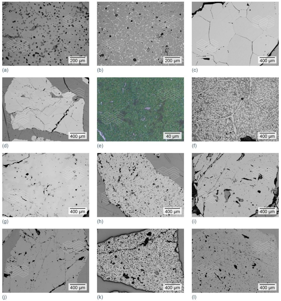
Postmortem findings need to be correlated with key brick properties, such as chemical composition, thermal shock behaviour, and thermal conductivity. The selection and combination of raw materials, together with precise pressing and firing conditions, determine the final refractory properties and play a decisive role in performance during application. Some of the main raw materials are illustrated in Figure 4, which provides an insight into their variety and use in refractories for ferrochrome and other ferroalloy furnaces.

Figure 4. Different types of raw materials, with an optimised particle size distribution, used in refractories for ferrochrome and other ferroalloy furnaces. (a) sintered magnesia (high-purity), (b) sintered magnesia (Mg,Fe)O, (c) fused magnesia, (d) chrome ore (Fe,Mg)(Cr,Al,Fe)2O4, (e) chrome oxide green, (f) fused magnesia chromite, (g) fused chrome corundum, (h) sintered alumina, (i) fused alumina, (j) andalusite, (k) bauxite, and (l) fireclay.
To assess refractories suitable for the slag zone in ferrochrome furnaces, thermochemical interface reaction calculations were performed for four different basic refractories: High-quality MgO-C, fired MgO, fired MgO-Al2O3, and fired MgO-Cr2O3. In addition, corrosion resistance experiments were conducted in a HFIF using two different FeCr slags (i.e., slag A and slag B) under defined temperature and atmospheric conditions to compare the performance of the basic refractory products and validate the modelling results. Process slags can vary significantly depending on the ferroalloy grade produced (e.g., types of raw material and process conditions) and a composition range is given in Table I. The slags employed in the experiments differed in their MgO content.
Figure 5 shows the interface diagram calculated for MgO-C and a representative FeCr slag. According to the thermochemical model, an olivine phase and Mg-spinel formed as reaction products of MgO with SiO2 and Al2O3 in the slag, as well as FeCr reduction from the slag. Similar to the previous calculation, FactSage predicted olivine and Mg-spinel formation for fired MgO material (Figure 6).
As shown in Figure 7, the FactSage calculation indicated that Cr and Fe in the MgO-Cr2O3 refractory are reduced to metallic phases at the selected temperature and pressure conditions with a representative FeCr slag. In addition, forsterite (i.e., Mg-rich olivine) and Mg-spinel were also predicted as reaction products of the refractory with the SiO2– and Al2O3-rich slag. In the case of MgO-Al2O3, olivine and Mg-spinel, as well as a slight FeCr reduction were modelled and can be seen in Figure 8.
Macroscopic images of the 4 different basic refractory fingers after the HFIF corrosion resistance test with FeCr slag A are depicted in Figure 9. No chemical or mechanical wear was observed in the fingers, although slight crack formation was detected in the MgO-Cr2O3 specimen that was probably due to thermal shock during the test. One reason for the excellent performance of these refractory materials was that the FeCr slag A was saturated with MgO; therefore, the MgO present in the fingers was in equilibrium with the slag bath. Micro XRF elemental mapping results of Si and Al in the cut samples indicated that while the FeCr slag was adhered to the fingers only minimal infiltration had occurred (Figure 10).
Photographs of the four investigated basic refractory specimens after the HFIF corrosion test with FeCr slag B can be seen in Figure 11. In general, all the basic refractories showed good performance when in contact with the FeCr slag B, as no severe corrosion was observed at a macroscopic level. Nevertheless, the fingers did not present such an intact surface as the ones after the corrosion test with FeCr slag A, particularly the tip region of the MgO-Cr2O3 and MgO-Al2O3 fingers. These differences observed between the two corrosion tests indicate that even small variations in the chemical composition of FeCr slags can significantly influence the performance of different basic refractories.
The elemental distribution of Mg, Si, and Al in the specimens after the corrosion test with FeCr slag B can be seen in the micro XRF images (Figure 12). On the one hand, the fired MgO and MgO-Al2O3 products showed a more original finger section compared to the fired MgO-Cr2O3 and MgO-C specimens, nonetheless crack formation was observed in the microstructure (Figure 12a). On the other hand, the MgO-C finger was not infiltrated at all compared to the fired products; however, the product matrix dissolved faster than in the case of the other three refractories.
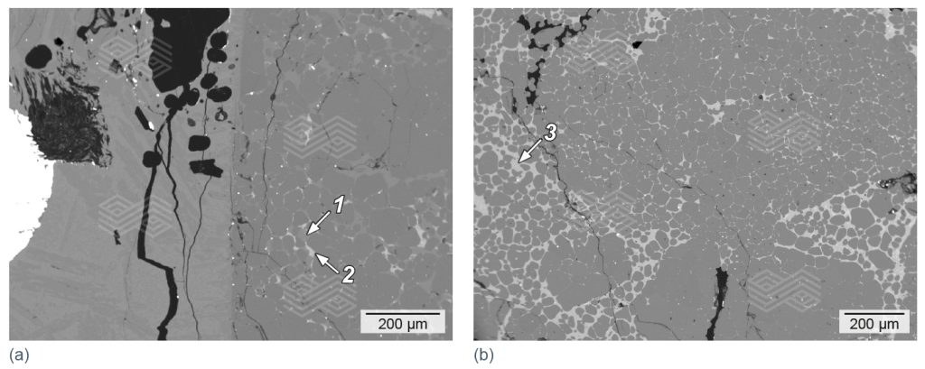
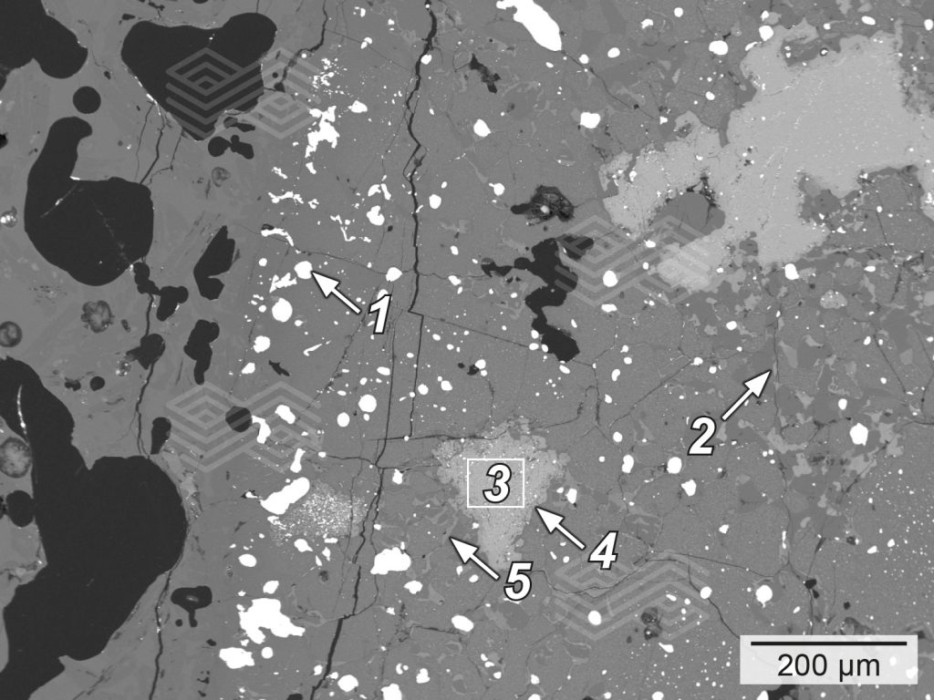
A mineralogical investigation of the specimens after the corrosion test with FeCr slag B revealed a lower infiltration in MgO-C compared to MgO, MgO-Al2O3, and MgO-Cr2O3. Although in the case of MgO-C, magnesia had reacted with the SiO2– and Al2O3-rich slag, the infiltration was very low due to the graphite protection (i.e., ~1–1.5 mm infiltration depth). In contrast, infiltration of MgO, MgO-Cr2O3, and MgO-Al2O3 and was clearly visible in the micro XRF images for silicon (see Figure 12b). Due to the high amount of SiO2 in the slag, the main reaction products in fired MgO were forsterite, monticellite, and a Ca-Mg-Al-silicate phase (Figure 13). This indicated that forsterite formation was possible in the infiltrated areas with SiO2. However, the modelled Mg-spinel formation was not observed microscopically. Investigation of the MgO-Cr2O3 sample showed severe reduction of Fe- and partly the Cr-oxide, which was predicted in the thermochemical calculations (see Figure 7). The presence of FeSimet was also detected under the microscope; however, it was not visible in the interface reaction diagram (Figure 14). In addition, forsterite (olivine) and Mg-spinel were observed microscopically, and both phases were predicted by FactSage calculations. In the case of the fired MgO-Al2O3, scanning electron microscopy identified forsterite and Mg-spinel in the highly infiltrated sample, as predicted in the FactSage calculation (see Figure 8), as well as a Ca-Mg-Al-silicate phase (Figure 15).

Figure 13. Scanning electron micrographs of fired MgO after a corrosion resistance test with FeCr slag B. In the highly infiltrated sample the main reaction products identified were (a) forsterite (1), Ca-Mg-Al-silicate (2), and (b) monticellite (3).

Figure 14. Scanning electron micrograph of fired MgO-Cr2O3 after a corrosion resistance test with FeCr slag B. In the highly infiltrated sample the main reaction products identified were (a) FeSimet (1) forsterite (2), reduced chromite and Femet (3), Mg-spinel at chromite rims (4), and monticellite (5).
As a leading supplier of refractory materials for the ferrochrome industry, RHI Magnesita offers a wide range of products, including alumina, alumina-chromite, magnesia, magnesia-carbon, magnesia-chromite, and carbon blocks. Selecting the appropriate refractories for ferrochrome furnace linings is essential to optimising the efficiency, service life, and operational costs of these high-temperature units. Therefore, RHI Magnesita has established a robust methodology that provides the foundation for constructing furnaces with cost-effective, long-lasting refractory linings. This approach includes modelling, corrosion investigations with customer-specific metals and slags, as well as industrial validation, complemented by postmortem mineralogical investigations.
For example, to determine refractories suitable for the slag zone in ferrochrome furnaces, corrosion tests were performed in a HFIF with four different basic refractories and two different FeCr slags. Evaluation of the results revealed that MgO-C based materials exhibited the least infiltration compared to fired MgO, fired MgO-Al2O3, and fired MgO-Cr2O3 under these conditions; however, the continuous wear kinetics were faster in the case of MgO-C, indicating that the original product suffered more rapid deterioration. In comparison, the MgO and MgO-Al2O3 products maintained a superior matrix integrity. The corrosion resistance tests were complemented by FactSage calculations, and the good correlation observed indicates that FactSage can serve as a reliable forecasting tool or validation method. Ultimately, the experimental results showed that refractory material requirements and performance were highly dependent on slag chemistry and, therefore, customer-specific due to the variation in ferroalloy slag compositions. By applying the aforementioned methodology, customer requests can be effectively met, ensuring optimal outcomes by selecting the most appropriate refractory solutions.
[1] Grand View Research, Inc. Ferroalloys Market Analysis, 2017–2028. San Francisco, USA, 2021.
[2] Gasik, M. Handbook of Ferroalloys, Theory and Technology; Butterworth-Heinemann: Oxford, 2013.
[3] Steenkamp, J.D., Reynolds, Q.G., Erwee, M.W. and Swanepoel, S. Freeze-Lining Formation in Submerged Arc Furnaces Producing Ferrochrome Alloy in South Africa. The Minerals, Metals & Materials Society. TMS 2019 148th Annual Meeting and Exhibition Supplemental Proceedings, 1161–1180.
[4] Bale, C.W., Chartrand, P., Degterov, S.A., Eriksson, G., Hack, K., Ben Mahfoud, R., Melançon, J., Pelton, A.D. and Petersen, S. FactSage Thermochemical Software and Databases. Calphad. 2002, 26, 189–228.